
Mechanical model validation with geometry-linked UFF data
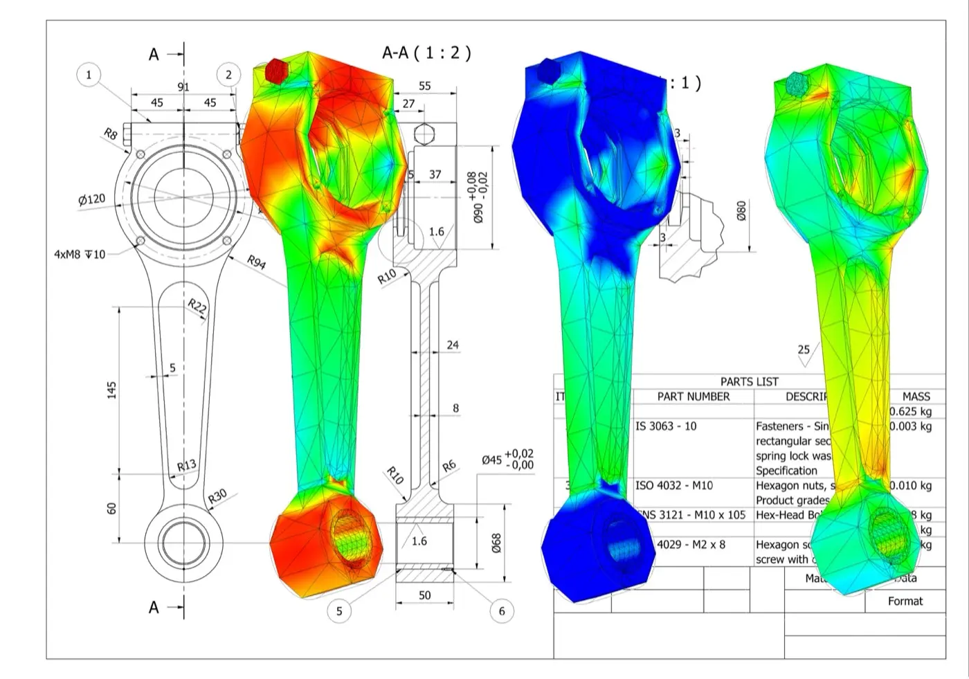
One UFF handoff
Geometry, waveforms and FRFs
XYZ coordinates, tri-axial velocity waveforms and FRFs remain associated with each measurement record.
A direct path from test to FE correlation
1. Define
Set the geometry, test points, response directions and excitation reference.
2. Measure
Capture dense non-contact velocity data and combine it with force, acceleration, displacement or strain references.
3. Correlate
Review modes, frequency and damping estimates, FRF overlays, MAC, COMAC and other correlation indicators.
4. Update
Focus the model on the joints, boundaries, material properties and local stiffness that drive the mismatch.
Keep response location and direction intact
Link point and response
Geometry and response records arrive together, so channels do not need to be reconstructed against coordinates.
Preserve direction
XYZ output identifies the response direction at each test degree of freedom.
Start analysis sooner
Import the test model and move into visualisation, parameter estimation and correlation.
See the regions that drive the mismatch

Complex structures
Cover panels, assemblies, frames and larger structures with the spatial detail needed to interpret the measured response.

Small components
Measure local mode shapes where conventional sensor placement is intrusive, impractical or too sparse.
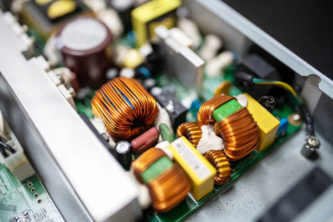
Measure small features without a dense sensor array
Use Laser RADAR for coverage and retain the complete test model
UFF export
Transport test geometry and structural-dynamics data into the modal and correlation environment your team uses.
Geometry-aware review
Open a test model with points, directions, waveforms and FRFs linked before animation or correlation begins.
Your analysis workflow
Keep your existing analysis package, naming conventions and validation criteria.
Resources for the next model-validation decision
Full-field modal-analysis workflow guide
Follow the end-to-end workflow from excitation and FRF acquisition through curve fitting, MAC review and UFF export.
Impact-test application note
See an impact-hammer test on a concrete slab using 65 simultaneous response measurements and geometry context.
PCB vibration application note
Explore high-density response measurement on populated electronics where local component behaviour drives qualification risk.
Products and application context
Q2 Laser RADAR
For complex parts, dense dynamic coverage and integrated 3D geometry in one measurement workflow.
Q1 Laser RADAR
For large or difficult-to-access structures that need stand-off geometry capture and vibration insight.
Acoustics, noise and vibration applications
Browse vibration, modal-testing and NVH applications by engineering question, structure and measurement constraint.
Practical answers before you plan the test
L’esportazione può mantenere insieme geometria, coordinate e risultati vibrazionali Q-Series per strumenti compatibili, inclusi risposta e FRF quando la prova fornisce il riferimento d’ingresso necessario. Confermare dataset UFF, unità, convenzione delle coordinate e requisiti dello strumento ricevente per versione e flusso.
Una FRF collega la risposta strutturale misurata a un ingresso misurato in frequenza. In una prova modale con martello o shaker aiuta a identificare risonanze, stimare parametri modali e confrontare il test con un modello a elementi finiti. Uno spettro di sola uscita non è automaticamente una FRF.
Sì, se la forza del martello è acquisita come riferimento d’ingresso allineato nel tempo e Laser RADAR registra la risposta sulla geometria scelta. Trigger, tempi, direzioni, banda, finestratura e qualità della forza vanno controllati prima di calcolare o esportare FRF.
Allineare sistema di coordinate, punti, direzioni di risposta, unità, condizioni operative e al contorno, banda e grandezza confrontata. Una corrispondenza chiara rende significative le differenze di frequenza naturale, smorzamento, forma modale e FRF invece di artefatti di setup.
Sì. Gli ingegneri possono esaminare FRF o parametri modali misurati, confrontarli con le previsioni e guidare gli aggiornamenti con le differenze. Il software non valida né aggiorna automaticamente il modello; parametri, criteri e interpretazione restano parte dell’analisi.
No. UFF è un formato di scambio che accelera il passaggio di geometria e dati compatibili. Identificazione modale, correlazione, aggiornamento, revisione dell’incertezza e report richiedono ancora software adatto, metodo definito e giudizio ingegneristico qualificato.