
Mechanical model validation with geometry-linked UFF data
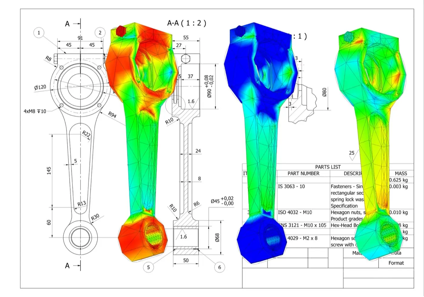
One UFF handoff
Geometry, waveforms and FRFs
XYZ coordinates, tri-axial velocity waveforms and FRFs remain associated with each measurement record.
A direct path from test to FE correlation
1. Define
Set the geometry, test points, response directions and excitation reference.
2. Measure
Capture dense non-contact velocity data and combine it with force, acceleration, displacement or strain references.
3. Correlate
Review modes, frequency and damping estimates, FRF overlays, MAC, COMAC and other correlation indicators.
4. Update
Focus the model on the joints, boundaries, material properties and local stiffness that drive the mismatch.
Keep response location and direction intact
Link point and response
Geometry and response records arrive together, so channels do not need to be reconstructed against coordinates.
Preserve direction
XYZ output identifies the response direction at each test degree of freedom.
Start analysis sooner
Import the test model and move into visualisation, parameter estimation and correlation.
See the regions that drive the mismatch

Complex structures
Cover panels, assemblies, frames and larger structures with the spatial detail needed to interpret the measured response.

Small components
Measure local mode shapes where conventional sensor placement is intrusive, impractical or too sparse.
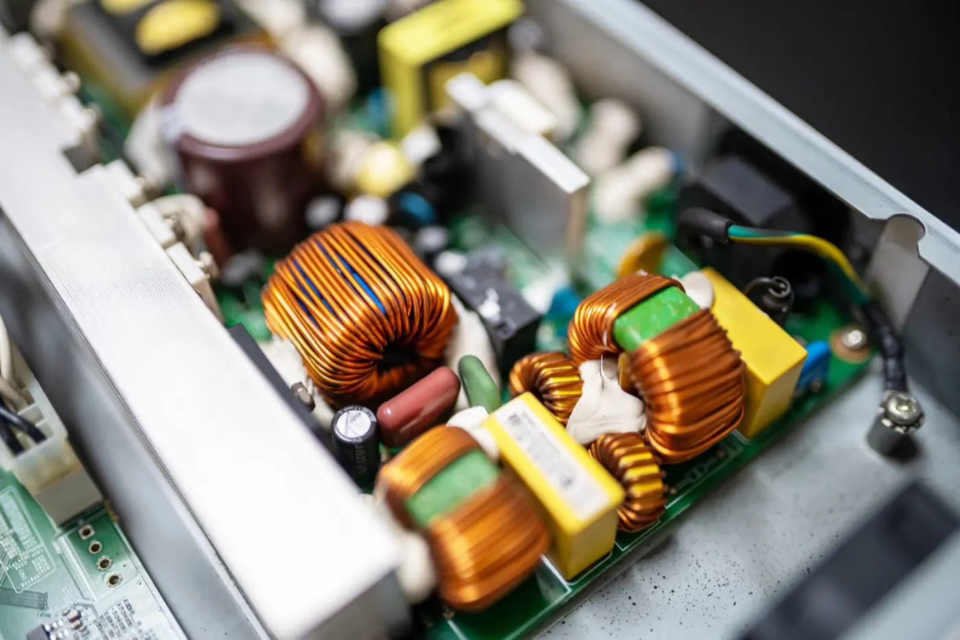
Measure small features without a dense sensor array
Use Laser RADAR for coverage and retain the complete test model
UFF export
Transport test geometry and structural-dynamics data into the modal and correlation environment your team uses.
Geometry-aware review
Open a test model with points, directions, waveforms and FRFs linked before animation or correlation begins.
Your analysis workflow
Keep your existing analysis package, naming conventions and validation criteria.
Resources for the next model-validation decision
Full-field modal-analysis workflow guide
Follow the end-to-end workflow from excitation and FRF acquisition through curve fitting, MAC review and UFF export.
Impact-test application note
See an impact-hammer test on a concrete slab using 65 simultaneous response measurements and geometry context.
PCB vibration application note
Explore high-density response measurement on populated electronics where local component behaviour drives qualification risk.
Products and application context
Q2 Laser RADAR
For complex parts, dense dynamic coverage and integrated 3D geometry in one measurement workflow.
Q1 Laser RADAR
For large or difficult-to-access structures that need stand-off geometry capture and vibration insight.
Acoustics, noise and vibration applications
Browse vibration, modal-testing and NVH applications by engineering question, structure and measurement constraint.
Practical answers before you plan the test
互換性のある後工程ツール向けに、測定形状、座標、Q-Series振動結果をまとめて保持でき、試験に必要な入力基準がある場合は応答とFRFデータも含められます。ソフトウェア版とフローに対して、UFFデータ、単位、座標規約、受信ツール要件を確認します。
FRFは、周波数ごとに測定した構造応答と測定入力の関係を表します。ハンマーまたは加振器によるモーダル試験で、共振の特定、モーダルパラメータ推定、有限要素モデルとの比較に使います。出力だけの振動スペクトルは自動的にFRFにはなりません。
はい。ハンマー力を時間同期した入力基準として取得し、Laser RADARで選択形状上の振動応答を記録します。FRFの計算や出力前に、トリガー、時刻、座標方向、帯域幅、窓関数、力信号品質を管理する必要があります。
座標系、測定位置、応答方向、単位、境界・運転条件、周波数範囲、比較量を一致させます。明確な対応により、固有振動数、減衰、モード形状、FRFの差を、設定やマッピングの人工的な差ではなく意味のある差として解釈できます。
はい。技術者は測定FRFまたは同定したモーダルパラメータをモデル予測と比較し、差に基づいて更新を検討できます。ソフトウェアがモデルを自動検証・更新するわけではなく、パラメータ選択、判定基準、技術解釈は解析の一部です。
いいえ。UFFは互換性のある形状と測定データの受渡しを短縮できる交換形式です。モーダル同定、相関、モデル更新、不確かさ確認、報告には、適切な後工程ソフトウェア、定義された方法、資格ある技術判断が必要です。