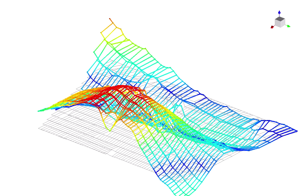
868 optical measurement points across the horizontal tail

See how the stabilizer and elevator move together. Dense optical measurements add local structural detail to conventional ground vibration testing.

In a comparative study with Simone Manzato and Alberto Garcia de Miguel of Siemens, Ommatidia measured 868 points across the horizontal tail of a B-Hunter drone. The optical mode shapes were consistent with conventional accelerometer measurements and revealed the relative motion of the tail and its control surface near 200 Hz.

tail mode deformed frame
Tail mode deformation from the original animation supplied by Simone Manzato; frequency unspecified in the clip. Grey wireframe: reference geometry. Original visualisation scale retained.

868

Scanned tail points

Near 200 Hz

Tail and elevator motion

3D geometry

Linked to vibration data

Measure the tail in its test environment

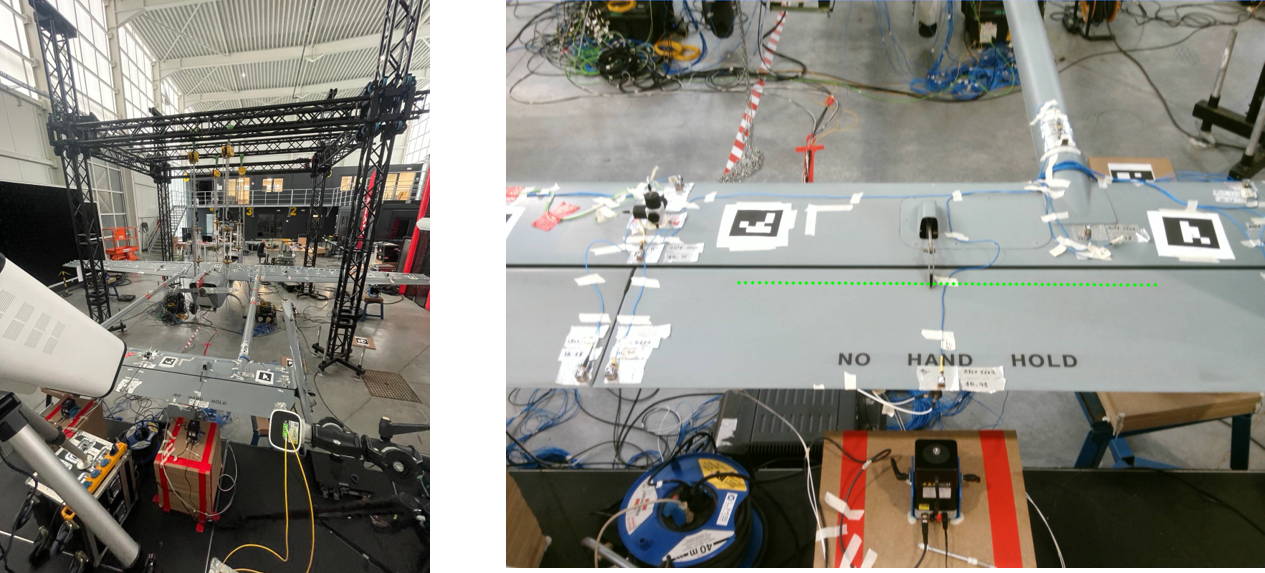
tail test setup
B-Hunter horizontal tail and optical measurement setup. Original photographs from the joint study, Figure 2.

Resolve local deformation across the tail

The conventional GVT campaign provided the aircraft’s global modal response. Ommatidia’s focused optical survey added spatial detail across the stabilizer and elevator while retaining the existing accelerometer instrumentation and shaker excitation.

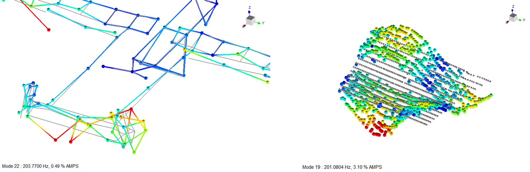
Near 200 Hz, the dense optical map makes out-of-phase motion between the tail and the elevator visible. The combination of measured geometry and vibration data connects the mode shape directly to the structure under test.

tail mode near 200 hz
Higher-order tail mode. Conventional measurements appear on the left; optical measurements appear on the right. Original source annotations are retained. Source study, Figure 5.

Animation supplied by Simone Manzato. Playback illustrates modal deformation; source identifier 190 is a file label. Original visualisation scale retained.

Geometry and motion in one workflow

The optical survey combined successive tail scans using a synchronized reference signal. Operational modal analysis then extracted the spatial response from the measured time histories.

For engineers studying control-surface coupling, the result is a detailed view of local motion alongside the global modes from the conventional campaign.

Explore the measurement and results

The PDF explains the test setup, acquisition and phase-reference workflow, operational modal analysis, stabilization diagram, and comparisons near 37 Hz and 200 Hz. It covers the reference elevator configuration shown in the study.

Related resources

Based on Laser Radar Vibrometry for Enhanced Drone full-field GVT: A Comparative Study, by Óscar Enríquez, Simone Manzato, Alberto Garcia de Miguel, Eduardo Margallo, Jose Luis Rubio and Grégory Pandraud. Study carried out by Ommatidia with Simone Manzato and Alberto Garcia de Miguel of Siemens. Photographs and result figures are reproduced from the joint study; animation supplied by Simone Manzato.

sales@ommatidia.tech

Copyright © 2026 Ommatidia LiDAR S.L. All rights reserved.

Ommatidia Upgrade & Trade-In Program

Upgrade to Ommatidia’s latest Laser RADAR technology and unlock more capability for your next measurement challenge. Whether you are expanding an existing setup or replacing an older system, we offer tailored upgrade options with discounts of up to 40%.

If you are currently using another manufacturer’s system, send us your model and measurement requirements. We will review your trade-in possibilities, identify the best Ommatidia configuration, and outline a practical upgrade path for your team.

Discuss your upgrade or trade-in