Full-Field Modal Analysis: Plan, Measure, Validate and Export

Full-field modal analysis

Plan the measurement. Validate the model.

A practical Q2 workflow for turning a planned coverage strategy, synchronized vibration data and geometry into a measurement package that can be reviewed, exported and correlated with a mechanical model.

Start with the engineering question: which modes, locations and response directions must be resolved? Then plan the views, measure the response, validate the data and hand it off without rebuilding the test model.

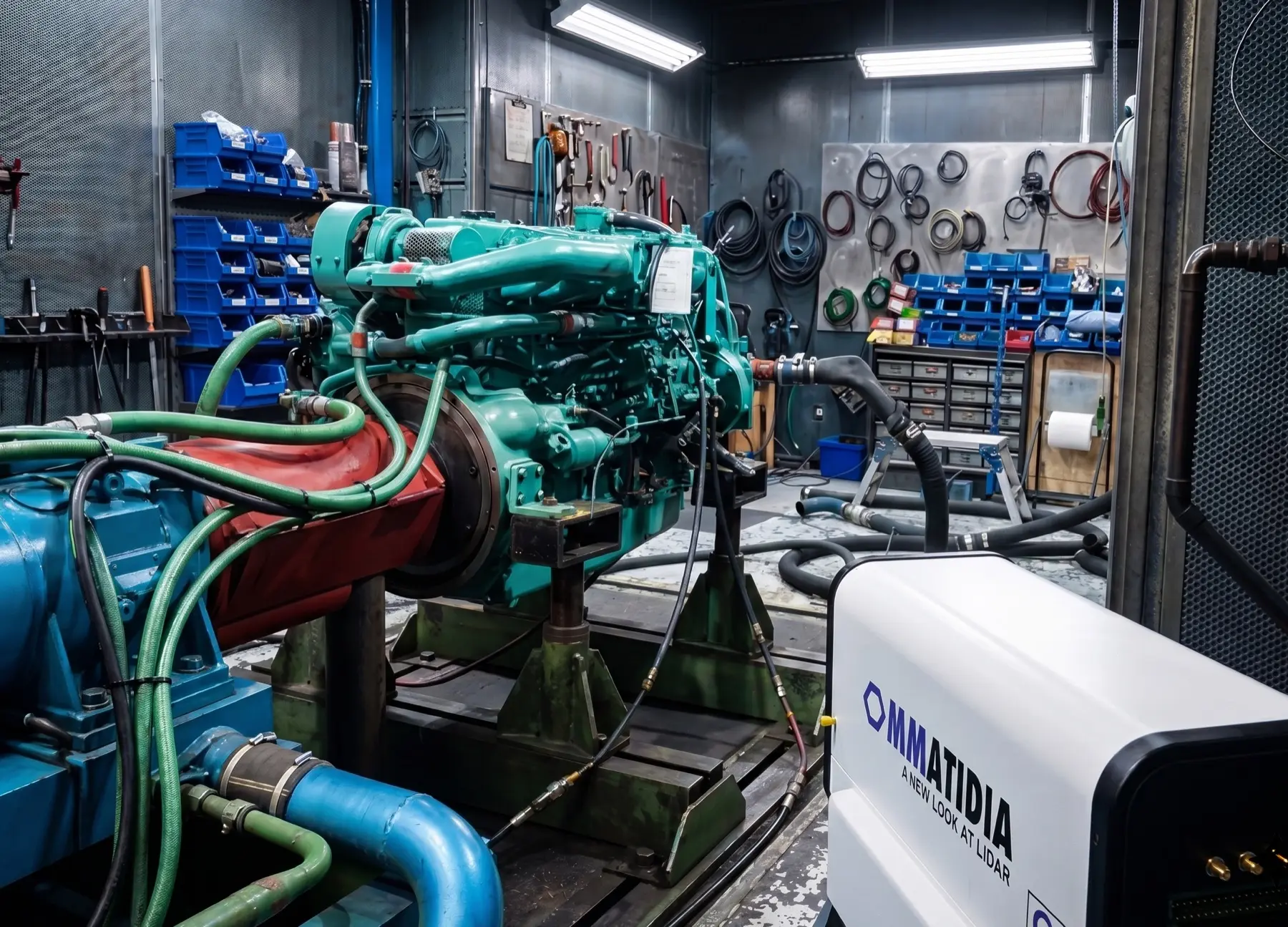
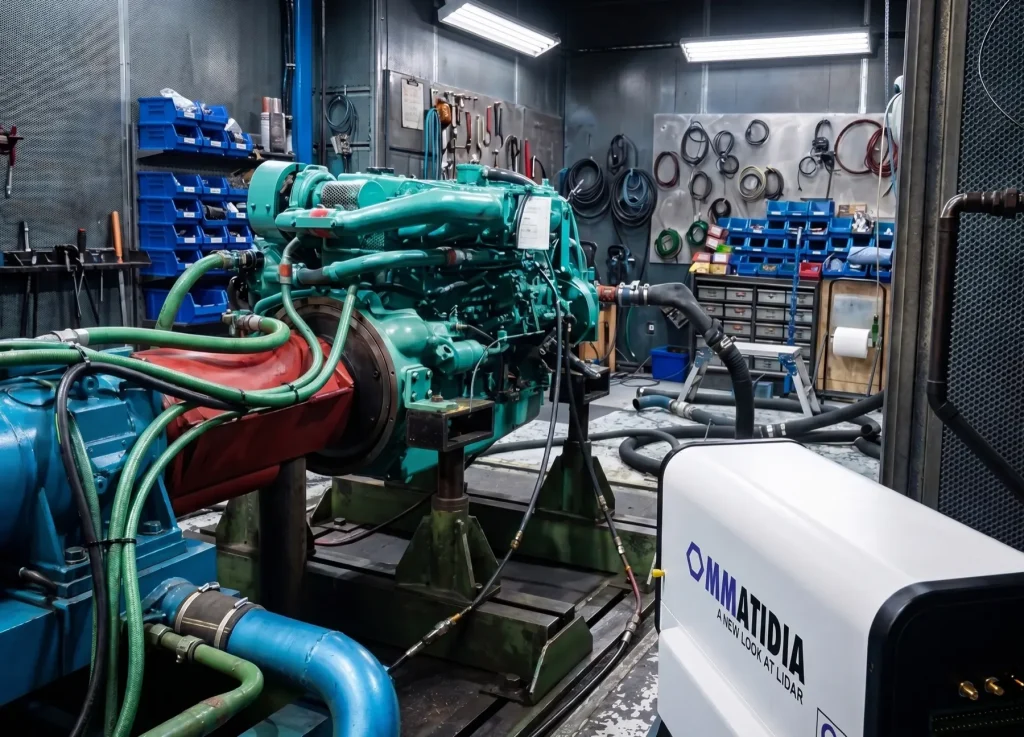
Ommatidia Laser RADAR measuring an aerospace turbine with a full-field scan

What modal analysis is—and what a usable test must preserve

Experimental modal analysis uses measured frequency response functions (FRFs) to estimate natural frequencies, damping and mode shapes. A usable result depends on more than a dense response map: the excitation reference, test geometry, response direction and signal quality must stay associated with the data.

That is why the workflow below does not end at a vibration image. It ends with a geometry-aware engineering handoff that supports mode-shape review, FRF comparison, MAC/COMAC and model updating.

Simulate before you measure

A coherent route from coverage plan to model correlation

Use prior simulation, operating knowledge or a preliminary test to choose viewpoints and spatial density. The goal is not to collect the most points—it is to resolve the structural response needed for the validation decision.

Five-stage full-field modal analysis workflow: plan, simulate, measure, validate and export

1. Plan coverage

Define the relevant frequency range, test geometry, response directions, expected mode complexity and the force or operational reference.

2. Simulate

Use a model or prior response to optimize view positions and check that the planned coverage can represent the response.

3. Measure

Capture registered geometry and synchronized non-contact velocity data while recording the required reference channels.

4. Validate

Review signal quality, spectra, repeatability and the spatial response before committing the test result downstream.

5. Export & correlate

Hand geometry, directions, waveforms and FRFs to the modal or FE workflow in a consistent UFF package.

Choose the analysis path from the test conditions

The measurement route must match the available excitation and the decision you need to make. A force-referenced test and an operational response test answer related but different questions.

Experimental modal analysis (EMA)

Use a measured force reference—such as an impact hammer or shaker—to calculate FRFs. Curve fitting then estimates modal frequency, damping and mode shapes for direct model comparison.

Operational modal analysis (OMA)

Use operational or ambient response when a controlled force reference is not available. OmmH5Viewer’s beta PyOMA2 workflow supports Frequency Domain Decomposition for reviewing mode candidates against the recorded geometry.

ommh5viewer spectrum
Review the dataset before the handoff

OmmH5Viewer keeps the analysis tied to the recorded Q-Series measurement

Atelier captures the Q-Series HDF5 dataset. OmmH5Viewer is the next stage: inspect frames, channels and metadata; isolate frequencies of interest; review spectra, spatial response and mode animation; then prepare the engineering export.

Validate before exporting

Use spectra, peak detection, intensity diagnostics, point-cloud-aware views and mode animation to examine the result in the context of the measurement.

Export a test model, not disconnected files

Geometry-linked UFF makes the correlation step usable

Ommatidia’s UFF handoff keeps XYZ geometry, tri-axial velocity waveforms and FRFs tied to the same measurement points and directions. Import the test model into the modal or correlation environment your team already uses instead of reconstructing geometry and channels by hand.

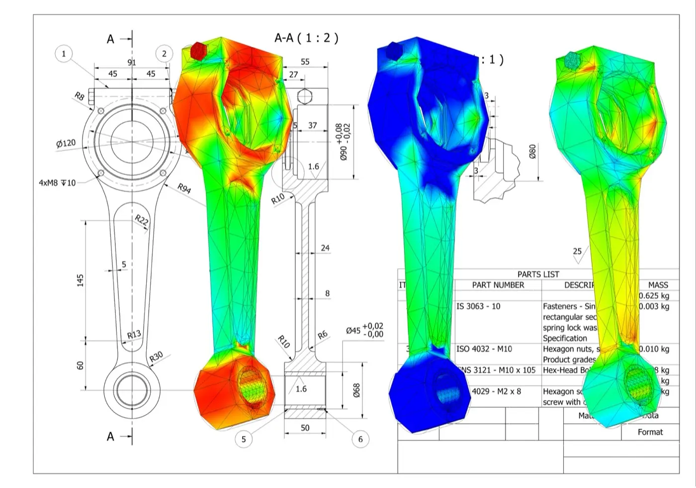
model validation fea contours

Correlation focuses the next iteration: joints, boundaries, material properties, local stiffness and other model assumptions that explain the measured mismatch.

What stays connected

Coordinates, response directions, dynamic waveforms and FRFs arrive together—ready for mode-shape animation, FRF overlays, MAC, COMAC and model updating.

What to validate before sign-off

Full-field coverage is valuable when it improves confidence in the engineering decision. Review these three layers before using the result to accept a model, diagnose a mismatch or plan a redesign.

Measurement integrity

Check the excitation or operational reference, signal quality, repeatability, frequency range and whether the chosen spatial grid captures the expected response.

Modal identification

Inspect FRFs or operational spectra, distinguish mode candidates from artefacts and review mode-shape plausibility, frequency and damping estimates.

Model correlation

Compare measured and predicted response with the criteria your team uses, including FRF overlays, MAC, COMAC and physically meaningful boundary assumptions.

Build the right modal test around your structure

Share the structure, expected frequency range, excitation method, access constraints and intended analysis handoff. We will help define the coverage, reference channels and data route needed for the modal-validation task.

Full-field modal-analysis questions

Keep the excitation, geometry, directions and response data connected from planning through model correlation.

What does experimental modal analysis estimate?

Experimental modal analysis uses measured frequency response functions to estimate natural frequencies, damping and mode shapes. A usable result also preserves the excitation or operational reference, test geometry, response direction, signal quality and uncertainty; a dense vibration image alone is not a completed modal test.

What are the five stages of this full-field workflow?

Plan the required coverage, simulate or use prior response to choose viewpoints, measure registered geometry and synchronized velocity with reference channels, validate signal quality and repeatability, then export and correlate the test model. Each stage should be defined by the engineering decision rather than point count alone.

What does the UFF handoff contain?

The documented Ommatidia handoff keeps XYZ geometry, response directions, velocity waveforms and frequency response functions associated with the same measurement points. This supports mode-shape review, FRF overlays, MAC, COMAC and model updating without reconstructing geometry and channel relationships by hand.

Is a 20-minute modal-analysis workflow guaranteed?

No. Twenty minutes is a workflow target, not a universal test duration or accuracy promise. Structure size, access, views, spatial density, excitation, frequency range, references, signal quality, repeats, processing and validation determine the actual time and whether the resulting evidence is adequate.